Adding a Tilt-up 9.8-hp Outboard Well to an Alberg 30

This Alberg 30 has a 9.8hp motor installed in a tilt-up outboard well. The prop is well positioned forward and low so as not to suck air in choppy water and can be tilted up for drag-free sailing. The prop aperture has been filled for low drag and improved rudder efficiency.
The Alberg 30 is one of those rare boats that has the perfect shape and dimensions for building a tilt-up outboard well in the lazarette locker with minimal modifications required. I have installed motor wells on both early and late-model Alberg 30s using either a 9.8-hp motor or a 6-hp Tohatsu, both with extra-long shaft. A benefit of using the smaller motor is that it is 35 lbs lighter, less expensive, easier to transport, and the well construction is simpler. The downside is you have less power to motor through adverse conditions, more engine noise and vibration from a single cylinder motor, and more limited thrust in reverse.
The question always arises if 6-hp or even 9.8-hp is enough for a 30-foot sailboat. That depends on your expectations and what type of sailor you are. As with everything on a boat, you need to be aware of the limitations. Top speed in calm conditions for the 6-hp motor is 5.5 knots but that drops off quickly in headwinds above 15 knots, particularly if there is much fetch for waves to build up. You could use a 20-inch long-shaft rather than the 25-inch extra-long shaft but that is not ideal because it will further reduce your speed in strong headwinds and the prop will come out of the water and suck air more easily in rough waters.
The 9.8 pushes an A30 at 6 knots or slightly more if the bottom is clean. Because of the discrepancies between inboard and outboard rated effective thrust, the 9.8 has nearly as much effective power as a typical two-cylinder inboard engine without the problems of wasted space, oily bilges, and the need either to become a proficient diesel mechanic or to bring one to your boat from time to time.
I still get a thrill each time I hoist sails on my Pearson Triton and tilt the motor up for drag-free sailing. I can relax as I sail right over those fisherman’s traps without fear of fouling a propeller. You’ll also win more races by not dragging a prop.
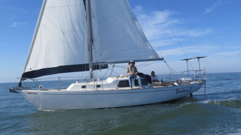
Alberg 30 with 9.8HP motorsailing in a near calm.
Getting started
Although I have installed 6-hp motors on both early and late-model Alberg 30s, here I describe fitting a 9.8-hp motor with an extra-long shaft to a 1968 model named Barbara J. The 6-hp outboard well is described in a separate set of instructions. Even though the bigger motor adds another 35 lbs and somewhat complicates the construction, many sailors prefer the extra power it provides to motor through more adverse conditions. I completed this project, with much appreciated assistance from my wife, while the boat sat on a trailer behind our house, but I have done other outboard wells while the boats were still in the water. With the boat in the water you have to shift weight forward to raise the waterline at the stern counter a safe distance for cutting through the hull and will need to climb into a dinghy at certain points. In any case, you need to haul out the boat at some point if you want to remove and seal the prop and close off its aperture to give less turbulence and best performance under sail.
If you have the skills it is possible to build the well with only these instructions and attached dimensioned sketches, but it will be easier and faster, with less chance of mistakes by using my full-size paper patterns kit. Email me for price ($95 as of April 2026) and availability. If you feel you are not up to the task, you might find someone like myself locally who is experienced in boat repairs that you can hire to assist you.
1. Once you have gathered your tools and materials listed below, cut out the paper patterns. Some of the patterns will be easier and more accurate to work with if you trace the paper to cardboard—you can determine that as you go.
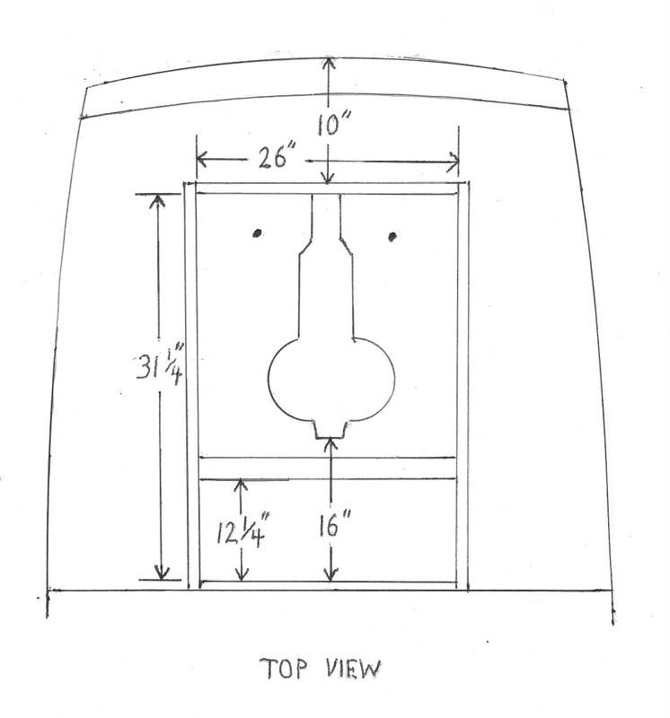
2. Having removed the broken inboard engine and all of its accessories, begin by enlarging the lazarette hatch opening to 26 x 31.25 inches (see sketch) using a circular saw and Sawzall.
Set aside the original hatch hinges to reuse with the new hatch. With that improved access now it’s easy to remove all the hardware attached to the afterdeck, including the mainsheet traveler and backstay chain plate. You may have old vents that should be removed and the holes in the deck glassed closed. This is also a good time to replace the original marginal 6-inch stern mooring cleats with 10-inch Herreshoff cleats. You can plug or remove and fiberglass over the old engine exhaust thru-hull fitting and cut away any hull liner on the newer version A30.
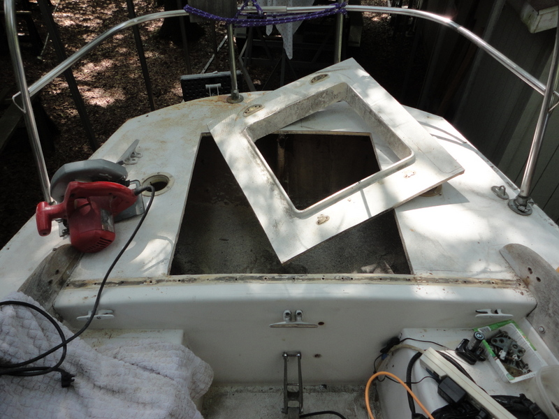
Cutting enlarged access to the lazarette.
3. Cut out the chain plate knee with a Sawzall and a metal cutting disc on an angle grinder. Then grind the inside locker surfaces with a 36-grit pad on the angle grinder to prepare the surface for epoxy and fiberglass. At this point patch the forward lazarette bulkhead with plywood and fiberglass where needed so that it is watertight from the bilge and side cockpit lockers. This ensures that in heavy weather the free-flooding area of the well does not allow water to enter other areas of the boat. If you are working with the boat in the water, doing this patch first will prevent the boat from sinking if waves come while the boat is at its mooring with the prop shaft hole cut in the hull.
4. To locate the correct slot location on the hull and transom for the motor shaft (or midsection) to pass through and then tilt up out of the water for storage or when under sail, clamp the motor to some sturdy surface such as a 2×10 clamped to the boat trailer frame or house porch rail and built a hull and transom mock-up around it of wood, cardboard, and plastic panels held by duct tape (see photo). Tilt the motor up and down and swivel side to side to simulate the correct slot shape in hull and transom. Once the motor is removed from the jig, lay the paper pattern of the hull cutout into the jig to confirm the optimum size and adjust the fit as needed, or otherwise transfer that shape to construction paper. Lay the paper pattern against the hull’s centerline to mark for cutting. By comparing the mock-up to the lazarette, confirm that the forward end of the hull hole should be 16 inches aft of the lazarette bulkhead. The thick fiberglass was tough work to cut, but I was able to get through it with a combination of angle grinder and Sawzall. No turning back now!
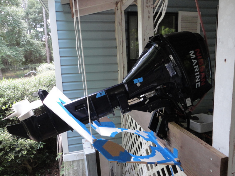
Forming a mock-up of hull and transom.
Motor mount jig and paper hull cutout pattern in place to mark for cutting hull.
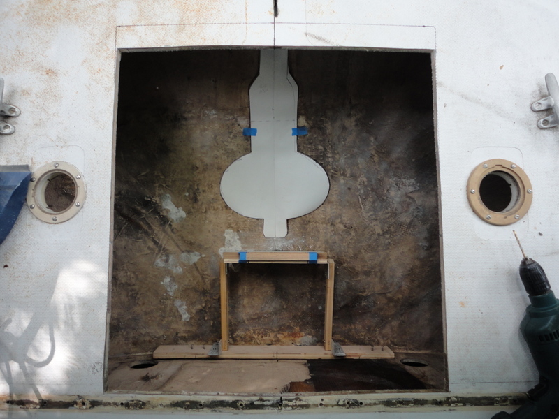
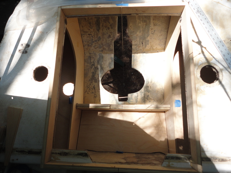
In order to check the fit of the motor in the boat, I built a temporary jig out of plywood, lumber, and pieces of aluminum angle screwed into the hull and forward bulkhead and made some final trimming of the slot so that the motor could swivel and tilt up. But you can skip that step and wait to fit the motor until after you fiberglass the vertical side panels in and then dry-fit the motor mount board to them. Through experience building and using other outboard wells on similar boats I found that the best compromise to keep the prop well below the waterline but not have the motor head too close to the water was achieved with the height of the jig at 8 1/2 inches. Use the pattern labeled “motor mount” to make this piece.
At close to 100 lbs, the motor is awkward for even two people to wrestle in and out of the well so you may want to use a boom vang tackle to make it easy. On boats that are in the water, I extend the boom by lashing the whisker pole to it and attach the vang under that. The motor is easier to insert into the well if you first remove the prop. The prop is reattached by tilting the motor up and leaning over the transom.
Putting it all together
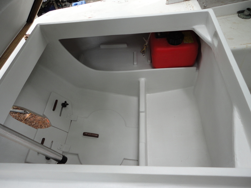
5. Measuring out from the centerline, place your cardboard patterns of the two longitudinal bulkheads according to the sketch, make corrections to the patterns by trimming or adding masking tape, and then trace them onto ½-inch marine plywood. Set at 26 inches apart to clear the motor when turned for side thrust, these panels serve as the inboard sides of the sealed lockers on top of which the two portable gas tanks sit. The panels are temporarily located in place by 3/4-inch stainless self-tapping screws going partway into the hull fiberglass and by wood .75 x 1.25-inch pine cleats screwed inside to the forward bulkhead. You can also use standard nominal 1×2 lumber which is .75 x 1.5 or rip them down on a table saw.
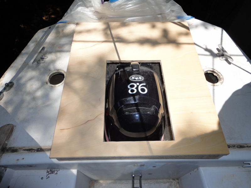
Test fitting the panels for the gas tank shelves and forward buoyancy chamber.
6. Fit the tops of the gas can shelves using the same method of cardboard patterns transferred to ½-inch plywood. Place the shelve tops 1.25-inch below the tops of the vertical bulkheads and angled down a few degrees forward and inboard to permit draining of any water to the lower part of the motor well through slots cut into the retaining lip. The shelves need to be at least 12.5 inches below the deck to allow clearance for inserting the 3.1 gal. gas tanks. The forward and inboard ends of these shelves are held in position by more wood cleats. Because the tops of the gas tank shelves are too large to fit past the vertical bulkheads, once the insides of the plywood are sealed in two coats of epoxy resin the tops are placed inside and clamped up out of the way until the vertical panels are glassed in. Then they are lowered into position and glassed in as well.
7. On my first outboard wells I glassed in each component before moving on to cutting and fitting the next panels, but it is faster if you dry fit most of the panels and then fiberglass them all at the same time as long as you allow extra clearance at the joints for fiberglass. Before applying the fiberglass, I brush epoxy resin on the surfaces and then apply epoxy thickened with colloidal silica by squeezing it out of the cut corner of a Ziploc freezer bag. Smooth the fillet with a rounded plastic spreader. The fiberglass layers go on more smoothly if done directly on top before the fillets harden.
Although they are considerably more expensive, high density fiberglass-reinforced polyurethane panels such as Coosa 20 or Baltek Airex PXc can be used instead of plywood in any areas. Cut, shape, fasten, and fiberglass over them as when using plywood, but without the need to add extra coats of epoxy and fiberglass just for waterproofing. Lighter foam boards such as 5 lb density Divinycell or Core-cell can be used to save weight but will require slightly more fiberglass and resin to obtain the stiffness required. Since even marine plywood is vulnerable to rot if it becomes waterlogged, be careful to apply at least two coats of epoxy resin to the inside of sealed locker panels, paying close attention to sides and edges and cover all exposed surfaces with fiberglass cloth. Areas that are joined to the hull are glassed in using at least three layers consisting of 2-, 4-, and 6-inch wide fiberglass tape. The motor mount board takes a lot of strain and vibration, so it receives five layers of cloth.
8. After the gas tank shelves are glassed in, insert the 1.25-inch laminated plywood transverse motor mount board as shown in the sketch and as confirmed by a line marked on the hull from the jig position and secure with screws. The 9-inch-high board was cut down ½-inch in the center as an indent to prevent the motor from vibrating out of position. Then set the motor back in to ensure adequate clearances and to get accurate measurements for the height of the lid and hatch framing. If the motor is blocked at the transom from fully tilting up, make adjustments to the motor mount board or hull cutout. If motor will not tilt high enough to engage its tilt lock mechanism, you can either shim it if this doesn’t place the shaft more than a couple degrees from vertical or by raising the top of the hull slot using a hole saw. If using a hole saw, first drill a hole in a small piece of plywood and clamp it in place as a guide for drilling the slot higher. You may have to tweak the fit again after fiberglass is finished.
The 6-hp motor only needs the framing to be 3 1/2 inches high but the larger 9.8 requires 8 inches of clearance above deck level. Instead of making the framing awkwardly tall, make it 3 inches high and then add a 5-inch raised center section of lid by laminating fiberglass and a ¼-inch plywood core inside a plastic storage bin of the correct size. If a suitable plastic bin is not available then fit 1/4” plywood panels, angled slightly out at the bases, secure with tape on one side and fiberglass the other side. Then remove the tape and glass the other side and glass the box to the lid.
I found that the motor throttle handle protruded above the motor head in the tilted-up position, so I cut one inch off the end of the handle in order to keep the hatch as low profile as possible. If you cut the rubber portion 1.5” from the end and then cut the aluminum handle at 1” you can save the rubber cap and fit it to the shortened handle using weatherstrip adhesive. After this test fit, remove the motor and glass in the motor mount.
The locker lid with cut-out is test fit around the motor.
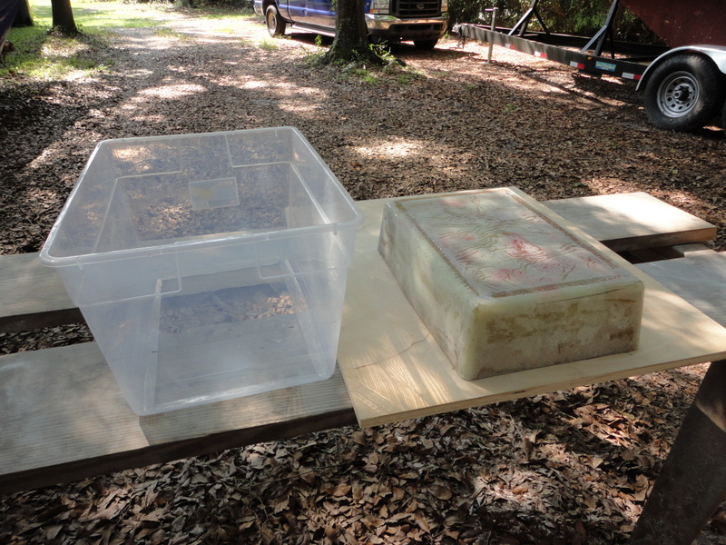
Using a plastic storage bin as a mold for the raised center portion of motor lid.
9. The hatch support flange, or sill, consists of four pieces of ¾ x 3-inch plywood stood on edge, or you can use solid lumber. First dry-fit the two side pieces using screws from underneath. Then set the end pieces in place, trace the deck camber on their bottom edges, cut them to fit, radius the edges, and glass all pieces inside and out. The aft sill received an additional outside framing of 1.5-inch height. That double thickness helps stiffen the deck, but to add even more support for the area that was cut out for the enlarged hatch, add a layer of ½-inch plywood under the aft center of the deck. When the teak trim is added to the lid the doubled framing gives a flush surface for installing the hinges between teak and sill. Just make sure that you leave some clearance under the taffrail flange to reach fasteners for the new external chain plate, mooring chocks, or other deck hardware.
10. With the motor in the tilted-up position, use a cardboard pattern to make two ½-inch plywood sliding boards to fit around the motor shaft and cover the transom slot. They each have a horizontal slot and a pair of 5/16-inch by 2 ½-inch flat head stainless steel machine screws countersunk from the outside of the transom and epoxied in place. Two knobs on the inside tighten to lock the boards in the open or closed position. The lower portion of the nearly circular hole in the hull is too wide to seal with sliding doors, so it gets covered by a plywood hull plug held by a wooden cleat forward and secured aft by two metal tangs on the sliding boards. The idea is not to make the hole watertight—that would be impractical—but to reduce the amount of surging water that enters when sailing in large seas and to allow the water that does enter to drain back out. The 6-hp motor has a smaller lower cowling, so the hull and transom slot is narrower and can be covered with a set of longer cover boards.
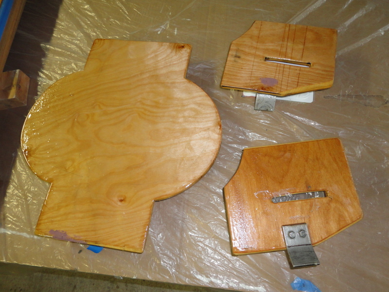
The two upper sliding cover boards and lower hull plug being sealed in epoxy resin.
11. Remove the motor one last time to construct a third buoyancy chamber between the motor mount board and the forward bulkhead. The ½-inch plywood panel is angled down to drain aft and just low enough so that the motor tension handles could be turned. Once it is glassed in place, drill 1-inch holes into the corners to allow any water that splashes over the motor mount board to drain into the motor well and back into the sea. Then add several coats of epoxy to holes to waterproof them. The plywood panel also adds significant strength to the high vibration loads on the motor mount board.
12. Cut out the ¾-inch plywood hatch lid and glue and screw strips of 3/4 x 1.5-inch teak hatch trim (or your choice of wood to be varnished or painted) to all edges. Glue the upper portion of the hatch sill board to the forward end of the hatch lid as in photo. Epoxy seal both sides of plywood. Optionally, add a thin layer of fiberglass to the top for longer lasting waterproofness against future gouges in wood but I haven’t bothered with that yet and haven’t seen any problem. Dry-fit hinges and latch.
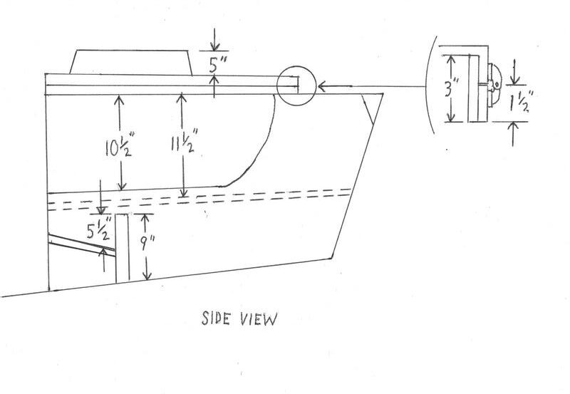
Side view of the completed motor well with cover boards in place.
Finishing details
13. Add eye straps and wooden cleats to the shelves to secure the gas tanks. Place gas cans on shelves at forward ends and mark for locations of ¾ x 1 x 10-inch pine cleats to hold cans from sliding outboard or aft. Remove gas cans and epoxy wood cleats in place.
14. To have future access to the sealed lockers under the gas tank shelves I fit 6-inch screw-out deck plates in the lower vertical bulkhead accessed from the cockpit side lockers. Since you no longer need access to the aft end of an inboard engine, an obvious future project would be to make the cockpit lockers watertight. Aside from protecting these areas from accidental flooding, sealing them off from the bilge means that you can more safely store fuel, including spare cans of gas for the outboard motor.
15. After sanding and fairing some of the rough fiberglass joints in the inside of the well, coat with any primer and paint but I prefer to just give it two coats of Interprotect 2000E epoxy barrier coat and leave it at that. Then sand, fair, prime and paint the afterdeck and outside modification areas with a two-part polyurethane. On the horizontal surfaces either add nonskid grit or KiwiGrip. Now or later you can repaint the entire deck nonskid for a better match.
16. The wiring from the motor’s electric start and alternator, as well as for the stern light and any solar panels, is run through a hole high in the forward bulkhead and sealed with caulking. If you are concerned about chafing you can run the wires through a cable clam, but I consider that unnecessary. A bilge pump outlet hose can be similarly run through the bulkhead with caulking to prevent leaks into the cockpit side lockers.
17. Now that the original backstay chain plate knee has been removed, fabricated a beefier replacement external chain plate from 1/4 x 1 1/2 x 12-inch stainless or bronze flat bar bent to fit over the taffrail. Keep in mind the motor lid only needs to open about 45 degrees. When you need more clearance for installing or removing the motor, the lid is removed by pulling out the hinge pins.
18. With the mainsheet traveler gone, add three-point end-of-boom sheeting tackle as seen in the materials list below.
19. Attach a tether and eye straps to prevent the hull hole plug below the sliding boards from being lost overboard during insertion or removal.
20. Add a latch for the front of the lid, rubber gasket under it, and the lid support spring. Warn all crew that the hatch lid is heavy and the spring could collapse at any time from vibration or an inadvertent bump so hands must never be allowed to rest on the frame when the lid is open or it could come down and break bones.
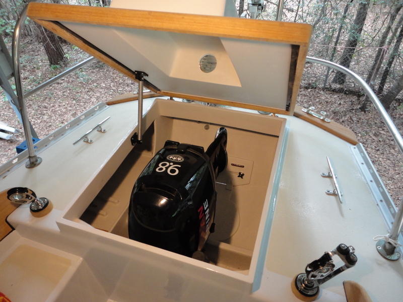
The 9.8-hp extra-long shaft Nissan installed in the completed well. New mainsheet tackle and 10-inch mooring cleats.
21. The motor is bolted to the mount to prevent it from vibrating out of position. Since these holes are in a wet area near the water, drill the holes oversize to ½-inch, inject thickened epoxy with a syringe, and then drill them for ¼-inch bolts.
22. The wiring from the motor’s electric starter and alternator, as well as for the stern light and two pole-mount solar panels, was run through a hole high in the forward bulkhead and sealed with caulking. If you are concerned about chafing you can run the wires through a cable clam, but I considered that unnecessary. A bilge pump outlet hose can be similarly run through the bulkhead with caulking to prevent leaks into the cockpit side lockers.
23. Although optional, it makes sense to fill in the prop aperture in the hull and rudder. This increases the boat’s performance by reducing drag and makes the rudder more effective. The aperture can be filled using foam board or laminated plywood, fiberglassed, and faired.
Performance
The 9.8 Alberg 30 outboard well has been sea trialed on numerous short passages offshore along the coast of Georgia and Florida as well as on a round-trip to the Bahamas. The performance was even better than expected, with the motor easily handling moderate waves and headwinds in ocean inlets. During a day of strong wind against tide in an inlet, the prop did briefly come out of the water a few times but not enough to force the boat to turn back. Another great feature is that these long keeled boats can be made to turn in their own length when swiveling the motor for side thrust—something that an inboard engine can never do.
In 2016, on another Alberg 30, I made a passage from Connecticut to Brunswick, GA with a 6-hp motor in a similar outboard well. We used the motor in a variety of conditions, including motorsailing 200 miles of the ICW from Norfolk, VA, to Beaufort, NC. A useful technique when encountering headwinds on any relatively underpowered sailboat is to reef the main, sheet it in tight, and motorsail in zig-zags some 20 degrees either side of the wind. With the mainsail adding drive and a steadying effect, the motor can supply enough thrust to push the boat forward at a surprisingly effective rate. On that trip we found that we averaged 10 miles per gallon at nearly full throttle. We carried extra gas cans that extended our range to 150 miles, which is more than most of us need to carry. Since there was plenty of space, the owner of Barbara J has added two more 3.1-gal gas tanks to make a total of over 12 gallons. When one tank is empty, or nearly so, we snap the fuel line onto another tank and carry on.
————————————————————————————-
A video of this project can be found at: https://www.youtube.com/watch?v=QnQU1c2qx4c
————————————————————————————-
Project time and costs: approx. 90–100 hours for one person with a second person assisting as needed. This project should not be attempted until you have practiced your skills on less complex boat repairs. The motor we used was purchased second-hand for $1,100 and the other materials cost about another $1,100. Even if you purchase the motor new, the cost, excluding your labor, is significantly less than that of a new diesel engine. Even so, I don’t necessarily recommend this modification just to save money since you might be able to rebuild or buy a replacement used diesel for similar cost and less labor. But if you appreciate the simple functionality of the outboard motor solution, then the relative low cost is a bonus.
Tools:
Drill with bits and countersink bit
4 1/2-inch angle grinder with metal cutting discs to cut fiberglass; backing pad and 36-grit discs for shaping
Jig saw
Reciprocating saw (Sawzall)
Circular saw or table saw with 60 tooth carbide tipped blade
5-inch orbital sander with 80, 120 grit paper
Router with ¼ and 3/8-inch round-over bits
3/8-inch forstner bit for bungs in teak hatch lid trim
1-inch and 2 ½-inch hole saws
Standard tool kit (hammer, wrenches, screwdrivers, etc)
Materials: (unless otherwise specified, many of these parts are sourced locally or from various online sources such as Amazon and Ebay)
Optional: Set of full-size paper patterns. Email me for price ($88 as of August 2021) and availability.
New or used Nissan or Tohatsu 9.8-hp outboard motor (2021 model MFS9.8BSPROEFUL) and two 3.1 gal. gas tanks (your local dealer, or onlineoutboards.com or try this link: https://onlineoutboards.com/collections/tohatsu-9-8-hp-outboards/products/2021-tohatsu-9-8-hp-mfs9-8bsproeful-outboard-motor )
Scrap cardboard to trace panel patterns. (If my patterns aren’t available to you then make a mounting jig to attach motor for measuring overall dimensions and tilting angles.)
Three 1 gal kits of your choice of epoxy resin and hardener, colloidal silica such as West System 406, and thickener to make a fairing compound like West Systems 407 (uscomposites.com, West Marine, etc).
One 4’x8’ sheet ½” plywood (use marine ply from your supplier). Ensure you seal all sides and edges of plywood with several coats of epoxy resin and epoxy barrier coat and cover with fiberglass cloth.)
One 4’x4’ half sheet of ¾” plywood (your lumber supply).
Plywood construction is easier and less expensive but if you want to save weight and eliminate any chance of water intrusion into plywood you can use 5 lb density Divinycell, Core-cell or Coosa covered in fiberglass cloth. You need to have experience using foam cores though because the core does not hold fasteners on its own and more fiberglass needs to be used so alternate construction methods beyond the scope of these instructions need to be worked out. (fibreglast.com)
Approx 4 yds. x 48″ medium weight (10oz) fiberglass cloth and at least one 10 yd roll each of 2”, 4” and 6” wide fiberglass tape. Add more fiberglass if using Divinycell or Core-cell foam sheet instead of plywood. (uscomposites.com, fibreglast.com, etc).
Three 3/4 x 1 x 8-foot pine or hardwood lumber
Two qts Interprotect 2000E white barrier coat
2-part primer and paint as needed for repainting afterdeck
One qt KiwiGrip or other nonskid paint
One 3/4 x 1 1/2 x 8-foot teak hatch trim
Assorted lengths between 1 and 2-inch long #10 flat head stainless sheet metal screws
One stainless plate 1/4 x 1 1/2 x 12-inch for new external backstay chain plate
One Moonlite Marine 0115 Big Hatch Holder spring (defender.com)
Two 5/16 x 2 ½-inch flathead machine screws and four stainless washers
Two 5/16-inch plastic knobs with threaded hole (mcmaster.com #5993K84).
Chromed brass latch
Four stainless eye straps and webbing with buckles or 1/4″ line to secure gas cans.
1/4 x ¾ x 6-foot rubber gasket
3M Black Super Weatherstrip Adhesive
West Marine Multi-caulk sealant or similar
Dust masks, gloves, goggles
Acetone, alcohol, rags, and paper towels
2 and 3-inch chip brushes and fiberglass roller
Mainsheet tackle from Garhauer—
One MS-SJ swivel jam with deck mount with 30-14US block with becket
One 30-19US single block with swivel standup deck plate
One 30-17US double block with adjustable shackle for end of boom
—————————————————————————